Suspension - 悬挂
- 非独立悬挂。轮轴之间被刚性连接。几乎只用在硬派的越野车上。
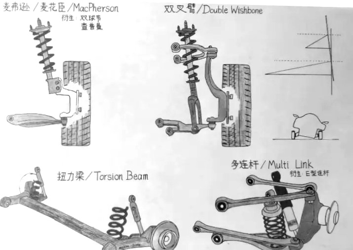
- 独立悬挂。每个轮子分别互不干扰。
- 麦弗逊悬挂(MacPherson)-只有上臂没有下臂(衍生:双球节、查普曼):(-)避振基本只能直上直下,操控性会略差;(+)最大程度的精简——轻且成本低;(+)给驱动空间,整体空间占用小。
- 双叉臂(Double Wishbone)-一上一下双臂(升级:多连杆MultiLink)。(+)车轮上下运动时候,可以动态改变轮子的外倾角,操控性提升;(-)结构复杂,成本高;(-)阻挡驱动,占用空间大。
- 半独立悬挂。
- 扭力梁(Torsion Beam):(+)成本低;(+)不占用空间;(-)舒适操控差;(-)不能四轮定位。
Wheel alignment - 四轮定位
关于汽车四轮定位和悬挂调校, Wheel alignment - what is camber, caster and toe?
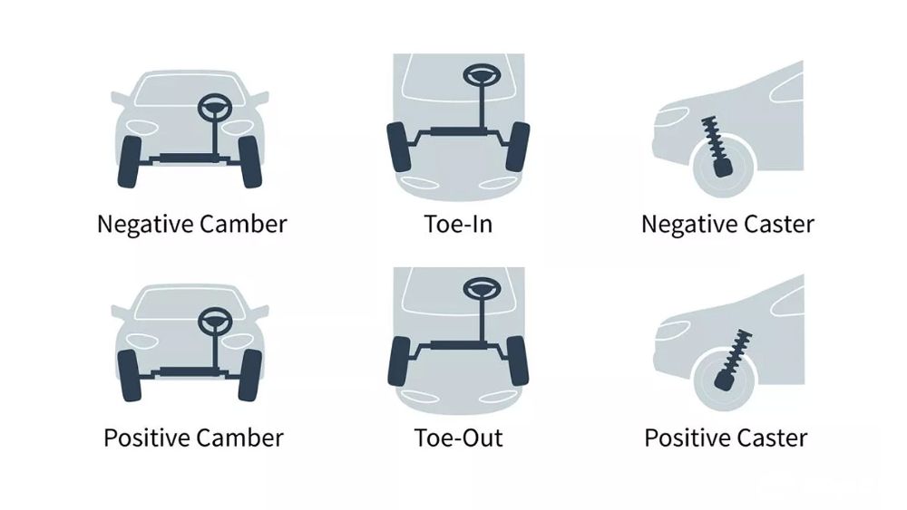
- Toe 前束 - 车轮前进方向的指向。
- 前轮Toe-in(内八字)走直线更稳定,后轮Toe-in转弯更稳。Toe-out使得车更敏感,潜在危险。
- Camber 侧倾角 - 车轮侧面和地面垂直线的夹角。
- 影响过弯的稳定性,调整轮胎的抓地。
- Caster 主销后仰角 - 转向运动时轴心与地面垂直线夹角。
- 增加caster,增加方向盘的稳定性。
Manual Transmission
How a Manual Transmission and Clutch Works
Wheel Speed Sensor (ABS)
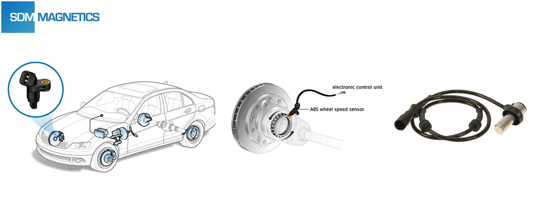
Wheel Speed Sensor Operation & Testing. The Difference Between Active and Passive Wheel Speed Sensors
- Passive Wheel Speed Sensor : 2 wire permanent magnet, produces an AC voltage signal, generated when a toothed tone ring passes by the sensor.
- Active Wheel Speed Sensor : look the same, (more accurate at lower speeds), output a digital signal DC square ware signal.
Electronic Control Unit

Understanding the CAN BUS - Part 1, Part 2 - Electrical Signals, Part 3 - The protocol, CAN synchronisation
- CAN (Controller Area Network) BUS
- Two twisted wires (twisted to reduce electromagnetic interference, and protect against the radio frequency interference) :
- Need be terminated at both sides by 120 ohms resistor (might be implanted in modules).
- Transceivers - transform the original signal to CAN HIGH (2.5V - 3.5V) and CAN LOW (1.5V - 2.5V) balanced signal (to make the message more recognizable).
- 0 : CanH = 3.5 V, CanL = 1.5V; 1 : CanH = 2.5V, CanL = 2.5V.
- Protocol
- Data Frame. broadcasted, all connected devices can receive. (with arbitration - lowest ID win)
- Remote Request Frame, require a can ID frame.
- Error Frame. one controller is detecting errors in a data frame received, it will send out error frame if error detected, and everyone else will ignore that data frame.
- Overload Frame. detection controller is busy.
ECU TESTING : Explained! CAN BUS Diagnosis – How to Troubleshoot Faults
- Information needed:
- OBD2 pin output.
- Full wiring diagram for vehicle - modules connected to can bus, where potential fail could lie.
- (1) Rule out a faulty battery.
- (2) Check the can bus network if asleep. (voltage between 6 & 14)
- (3) Test the can bus terminating resistance. (ohm between 6 & 14, should be 55-70Ω, since two 120Ω resistance at both end )
- (4) Diagnosing for each module. (60Ω or 120Ω reading, short to ground/voltage)
Unified Diagnostic Services (UDS) is a diagnostic communication protocol used in electronic control units (ECUs) within automotive electronics, which is specified in the ISO 14229-1.
Electrical Vehicle
EV Electrical Systems BASICS!, How an Electric Car Works?.
- High-Voltage System.
- Battery, Charger, Converter & Inverter (change the currency & regeneration), Motor.
- Low-Voltage System.
- Vehicle Accessories.
- Multiple CAN Networks.
Electric Vehicle Operation and Diagnosis
IPU - Integrated Power Unit
德赛西威(惠州 Desay SV 002920)三大业务:智能座舱(主要)、智能驾驶(IPU01-04)和网联服务。
IPU整车网关——只有它能把外部诊断请求转到内部各CAN子网。把原来分立的 电机控制器(MCU)、车载充电机(OBC)、DC-DC、高压配电盒、整车网关 做进一个铝壳,节省线束与接头。所有高压、动力、诊断报文都要经过它。