Other subjects also has sensor fusion related content, while the papers here are more specific with multi-sensor fusion.
Table of Contents
Lidar Image summary (2022)
we normally have two types of systems :
- lidar based : camera pose as initial estimation and as constrain. I personal perfer this one, since our system is generally lidar based.
- project lidar to camera, and form a vio odometry system. It wastes lots of calculation, I don’t think it is necessary to maintain two slam system.
- project camera information to lidar pts, to form lidar pts constrain. This seems more reasonable to me.
- camera based : lidar project to camera to offer depth
visual-lidar-imu (with vins vio odometry)
visual-lidar-imu (with direct method image odometry)
Compare R3LIVE++, LVI-SAM and Mine:
| R3LIVE++ | LVI-SAM | Mine |
|---|---|---|
| single system | two system | single system |
| Optical flow tracking | Slide window VIO : VINS-MONO | Direct sparse tracking |
| with photometric calibration | without | with photometric calibration |
| Filter based LIO (FAST-LIO2) | Pose Graph Based LIO (LOAM) | Filter based LIO (FAST-LIO2) |
2022
![]() R3LIVE++: A Robust, Real-time, Radiance reconstruction package with a tightly-coupled LiDAR-Inertial-Visual state Estimator, github code
following R3LIVE, with the camera photometric calibration and the online estimation of camera exposure time.
R3LIVE++: A Robust, Real-time, Radiance reconstruction package with a tightly-coupled LiDAR-Inertial-Visual state Estimator, github code
following R3LIVE, with the camera photometric calibration and the online estimation of camera exposure time.
2021
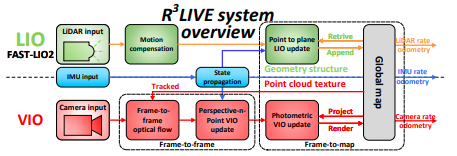
![]() R3LIVE: A Robust, Real-time, RGB-colored, LiDAR-Inertial-Visual tightly-coupled state Estimation and mapping package. Visual-Lidar-Imu filter.
R3LIVE: A Robust, Real-time, RGB-colored, LiDAR-Inertial-Visual tightly-coupled state Estimation and mapping package. Visual-Lidar-Imu filter.
- even though in its paper it said it has two system, it actually uses one single imu-based filter back bone. so it uses imu for filter predict, then has lidar and image measurements.
- use lidar pointcloud for VIO tracking, VIO system won’t optimize map points.
- finally use MVS to make mesh (delaunay triangulation), ‘texturing’ is to update pcl color with the raw lidar map.
![]() LVI-SAM: Tightly-coupled Lidar-Visual-Inertial Odometry via Smoothing and Mapping (looks similar to V-LOAM + IMU) optimization with the following factors (with two system) (It is actually not so tightly coupled):
LVI-SAM: Tightly-coupled Lidar-Visual-Inertial Odometry via Smoothing and Mapping (looks similar to V-LOAM + IMU) optimization with the following factors (with two system) (It is actually not so tightly coupled):
- Use lidar information in VINS (difference compared to VINS)
- use lidar odometry pose for vins initialization
- project lidar cloud to get vio feature depth neighbor pts model a plane,
- feature depth in vins is anchored by the first observation. so here depth from lidar also valid only for first observation.
- in marginalization if the marginalized pt has lidar depth, move its flags to the next.
- set depth constant if has lidar depth.
- Use vision in VIO-SAM (difference compared to VIO-SAM)
- use visual loop detection result as lidar loop candidate (to further process ICP).
- use VINS pose as initial pose for lidar registration.
My implementation: I use FAST-LIO2 base instead of V-LOAM base.
- looks good while the movement is not too dramatic.
- while VINS is not stable when movement (for an example in car), or scene has lots of moving objects.
2020
![]() CamVox, Lidar visual mapping using livox.
CamVox, Lidar visual mapping using livox.
- Livox generate dense lidar cloud, match visual edge with lidar intensity image edge for extrinsic parameters calibration.
- IMU for lidar un-distortion.
- Run ORBSLAM2 RGBD pipeline.
![]() Augmenting Visual Place Recognition with Structural Cues Use both image (e.g. NetVLAD 2016) and 3d cloud (e.g.
PointNetVLAD 2018) encoders.
Augmenting Visual Place Recognition with Structural Cues Use both image (e.g. NetVLAD 2016) and 3d cloud (e.g.
PointNetVLAD 2018) encoders.
![]() [Stereo Localization in LiDAR Maps]https://github.com/tony1098/Stereo-Localization-in-LiDAR-Maps). Localize stereo camera in pre-built lidar map.
[Stereo Localization in LiDAR Maps]https://github.com/tony1098/Stereo-Localization-in-LiDAR-Maps). Localize stereo camera in pre-built lidar map.
- Using ZED stereo camera, opencv (StereoSGBM and DisparityWLSFilter) to compute depth image.
- Registration using Nelder-Mead method.
![]() RGB2LIDAR: Towards Solving Large-Scale Cross-Modal Visual Localization DL match rgb image and depth image (from lidar cloud)
RGB2LIDAR: Towards Solving Large-Scale Cross-Modal Visual Localization DL match rgb image and depth image (from lidar cloud)
![]() Lidar-Monocular Visual Odometry using Point and Line Features (loosely coupled)
Lidar-Monocular Visual Odometry using Point and Line Features (loosely coupled)
- image -> point feature (ORB), line feature (LSD) -> project lidar to estimat depth -> odometry -> local BA current pose and landmarks.
- ICP relative pose factors.
- Global BA using ICP factors, ORB factors, LSD factors.
![]() LIC-Fusion 2.0: LiDAR-Inertial-Camera Odometry with Sliding-Window Plane-Feature Tracking Tracking planes in the sliding window.
LIC-Fusion 2.0: LiDAR-Inertial-Camera Odometry with Sliding-Window Plane-Feature Tracking Tracking planes in the sliding window.
2019
![]() CMRNet: Camera to LiDAR-Map Registration. Project a depth into plane (from an initial pose guess), CMRNet use RGB and depth as input, output 2D correspondings for each depth value. Finally PnP-RANSAC for pose estimation.
CMRNet: Camera to LiDAR-Map Registration. Project a depth into plane (from an initial pose guess), CMRNet use RGB and depth as input, output 2D correspondings for each depth value. Finally PnP-RANSAC for pose estimation.
2018
![]() LIMO: Lidar-Monocular Visual Odometry
LIMO: Lidar-Monocular Visual Odometry
- Depth estiamtion : project lidar into image -> estimate local plane (select local range, foreground segmentation) -> check the depth.
- Visual Odometry, global BA.
2017
![]() DSAC Differentiable RANSAC. replace non-differentiable parts of RANSAC algorithm with approximated differentiable parts (by soft argmax and probabilistic selection). Then make a deep learning DSAC. (As I understand, RANSAC is mathematically proved, I don’t understand how its accuracy can be improved).
DSAC Differentiable RANSAC. replace non-differentiable parts of RANSAC algorithm with approximated differentiable parts (by soft argmax and probabilistic selection). Then make a deep learning DSAC. (As I understand, RANSAC is mathematically proved, I don’t understand how its accuracy can be improved).